


Analog Devices / Maxim Integrated MAX22211 Dual H-Bridge for Motor Drives
Analog Devices MAX22211 Dual H-Bridge offers a dual 36V, 3.8AMAX H-bridge intended to drive two brushed DC motors or a single stepper motor. The H-bridge FETs have very low impedance, enabling high driving efficiency and low heat generation. The typical total RON (high-side + low-side) is 0.25Ω, and each H-bridge can be individually pulse-width modulation (PWM)-controlled employing three logic inputs (DIN1, DIN2, EN).
The ADI MAX22211 provides an accurate current drive regulation (CDR), limiting the start-up current of a brushed DC motor or controlling the phase current for stepper operation. The bridge output current is sensed by a non-dissipative integrated current sensing (ICS). Then, the current is compared with a configurable threshold (ITRIP). When the bridge current surpasses the ITRIP threshold, the MAX22211 implements the decay for a fixed OFF-time (tOFF). Four different Decay methods are featured (Slow Decay, Fast Decay, and two Mixed Decay modes). The non-dissipative ICS eliminates bulky external power resistors, which are generally required for this function, allowing a dramatic space and power saving compared with mainstream applications using external sense resistors.
The MAX22211 is housed in a small 5mm x 5mm TQFN32 package or a 4.4mm x 9.7mm TSSOP28 package.
Features
- Current ratings per H-Bridge (typical at TA = 25°C)
- ITRIP_MAX = 3.8A (maximum current setting for internal current drive regulation)
- IRMS = 2ARMS (recommended maximum RMS current per full bridge)
- Integrated current drive regulation
- ICS eliminates bulky external resistors and improves efficiency
- Current drive regulation monitor output pins (CDRA, CDRB)
- 4x decay modes are supported (slow decay, fast decay, and two mixed decays)
- Half Full Scale (HFS) pin to improve current control accuracy in the low current range
- Two H-Bridges with +36V maximum operating voltage; total RON (high-side + low-side): 250mΩ typical (TA = +25°C)
- Current sense output (current monitor)
- Fault indicator pin (FAULT)
- Low-power mode (Sleep mode)
- Protections
- OCP for each individual channel
- UVLO
- TSD TJ = +165°C
- 5mm x 5mm TQFN32 package and 4.4mm x 9.7mm TSSOP28 package options
Applications
- Stepper-motor drivers
- Brushed DC motor drivers
- Solenoid drivers
- Latched valves
Simplified Block Diagram

Related Development Tools
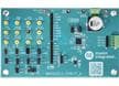
Analog Devices Inc. MAX22211EVKIT# Evaluation Kit
Proven design to evaluate the +36V, 3.8A Dual H-Bridge MAX22211 motor driver.
Related Products

Analog Devices Inc. MAX22217 Solenoid Drivers
Integrate functions aimed to optimize solenoid and DC motor drive control.